Automated Labeling of Lane Markers
The unsupervised LLAMAS (Labeled LAne Markers) dataset was generated automatically using map projections and reprojection optimizations. In the following, we are going to visualize the complete process of generating the lane marker labels step by step.
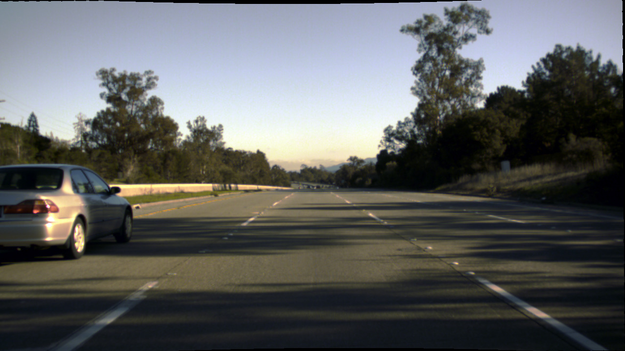
As a first step, we need an automated vehicle with extrinsically and intrinsically calibrated camera sensor(s). Recording camera images usually is fairly straightforward.
We also need a high definition map of lane markers that we can localize against. Such a map can be generated with a few drives over the same area. One important principle is that we only need to detect lane markers very close to our vehicle since we are going to closely pass all of them over time. At short distances, lane markers are mostly very easy to detect which we did with a lidar sensor, but that is not a necessity.
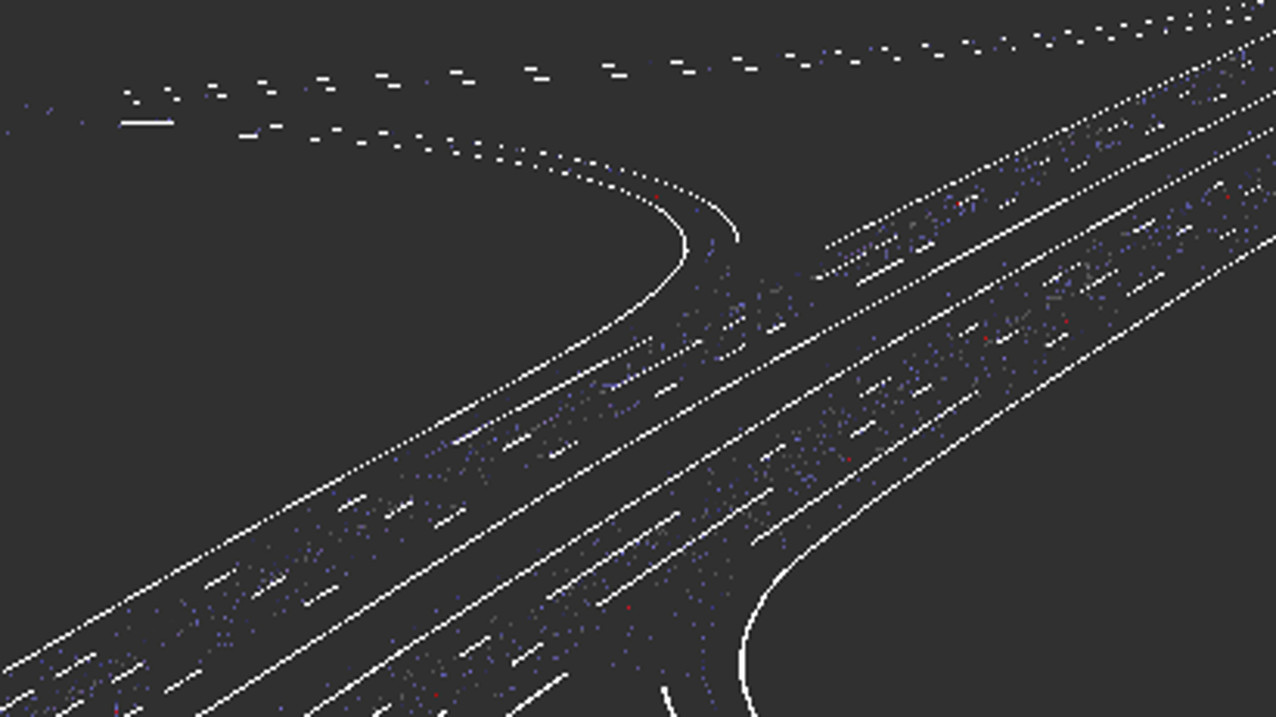
After localizing against the map, we can project the mapped markers into the image for arbitrary distances. Unfortunately, this projection is not going to be completely accurate because of inaccurate localization, calibration offsets, a moving suspension, and much more. Even small rotational offsets linearly increase with distance.
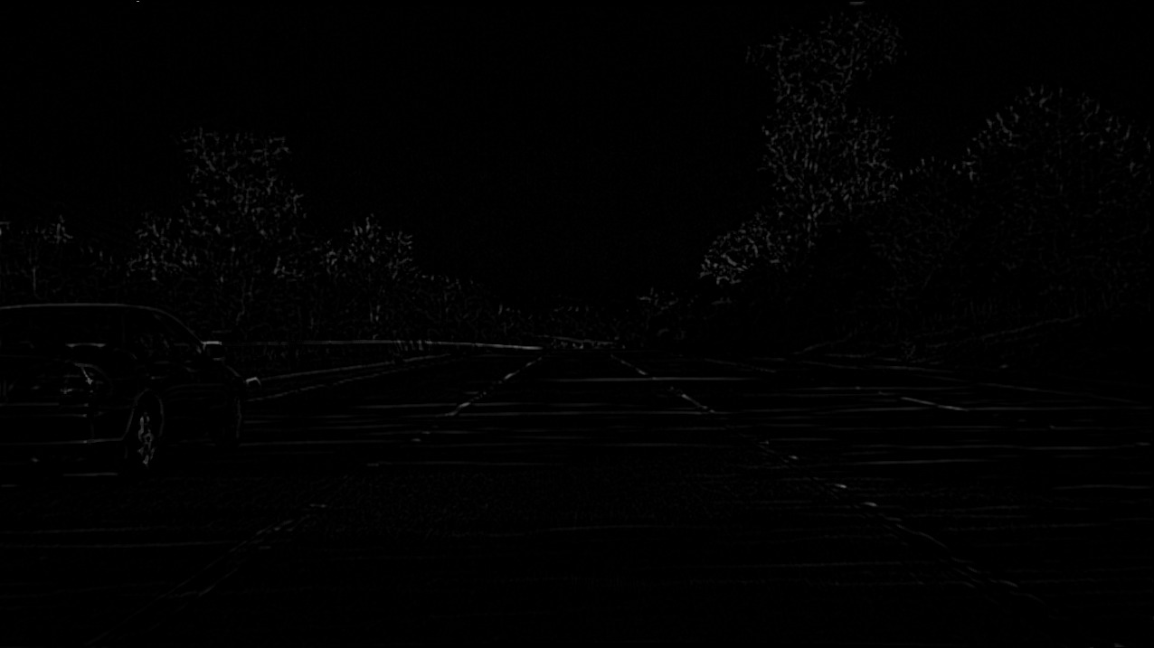
Without labels, we can already (poorly) detect lane markers using very straightforward methods such as edge detectors or the output from an applied top hat filter based on a 9x9 kernel as displayed above.
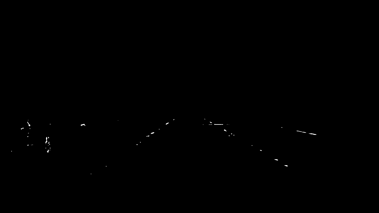
By thresholding the filter output and removing the upper parts of the image, we can already get a very simple lane marker estimate with only three lines of code.
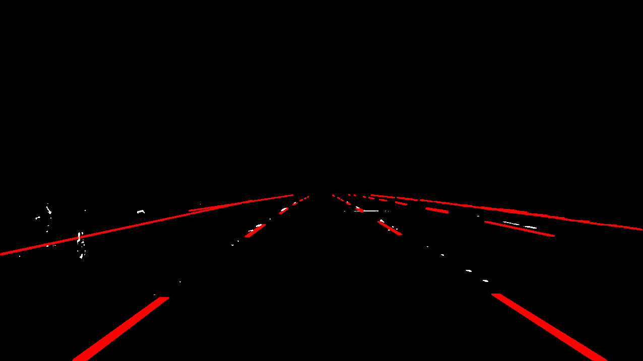
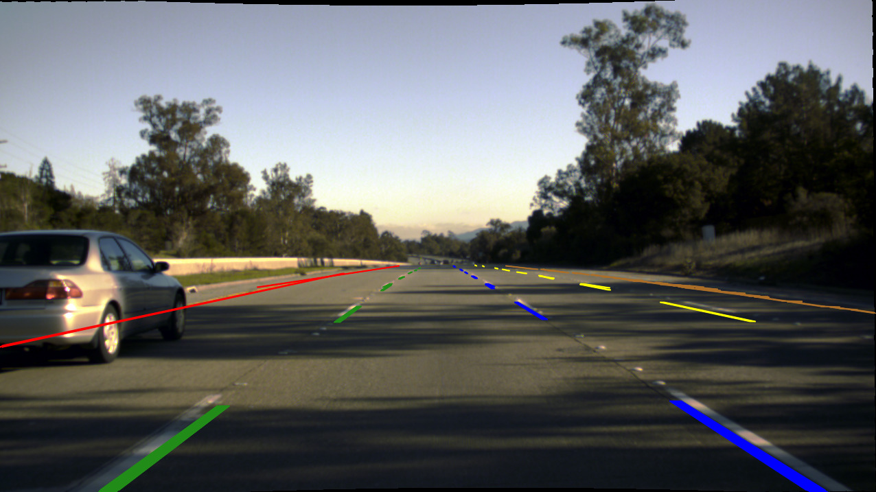
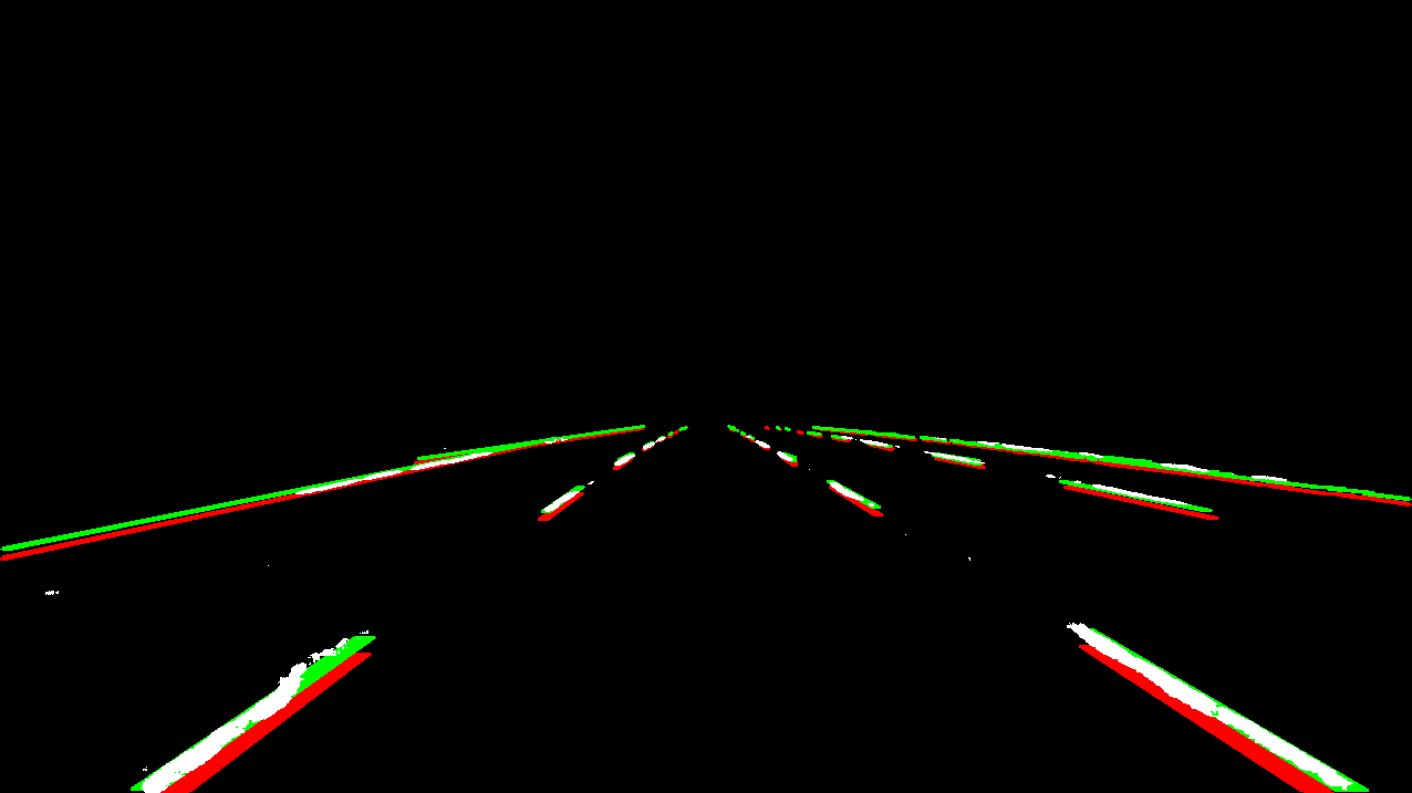
In this view, especially on the right, we can see an offset between detected (white) and projected markers (red) already.
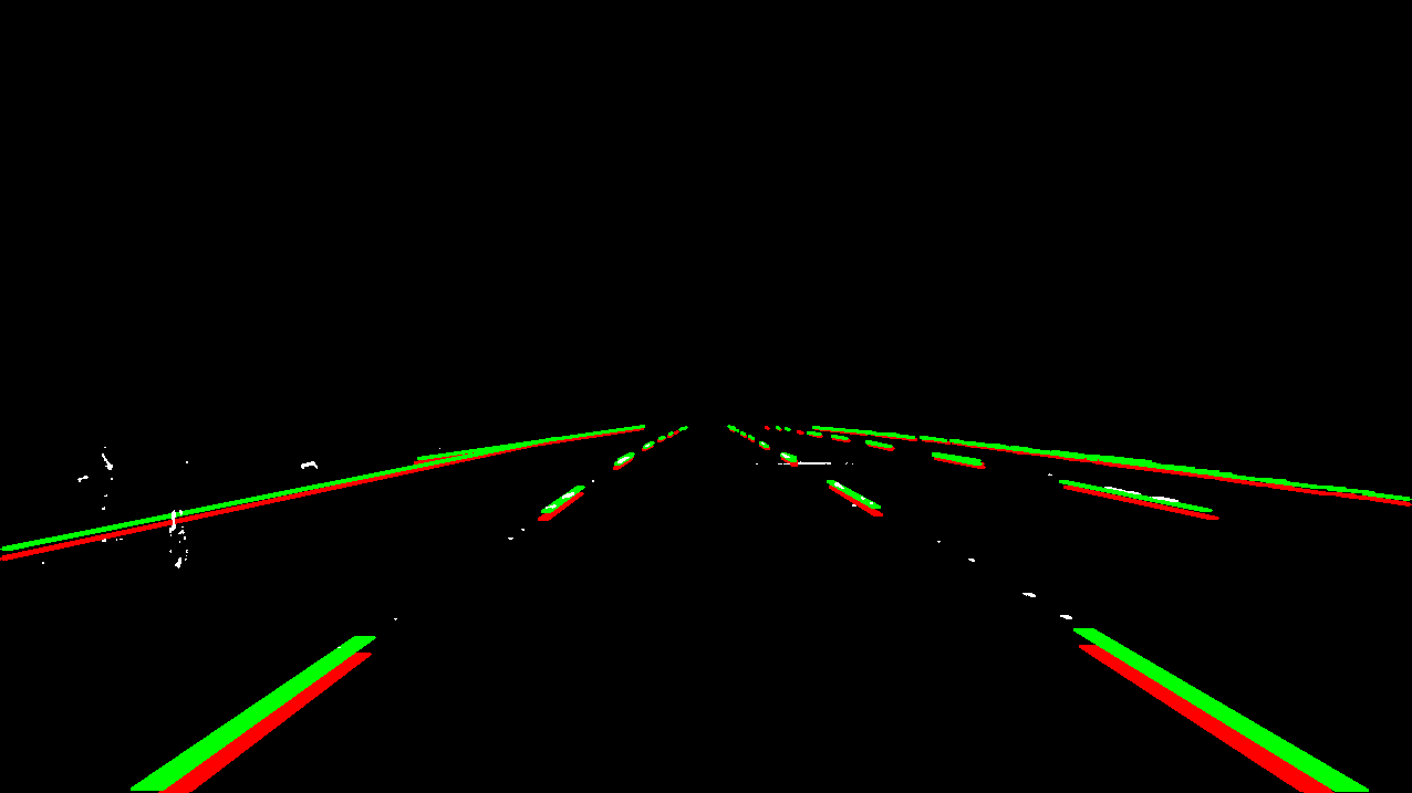
We can now optimize the marker projection from the map into the image to better fit the detected markers. The correct markers are displayed in green and can already be used as labels.
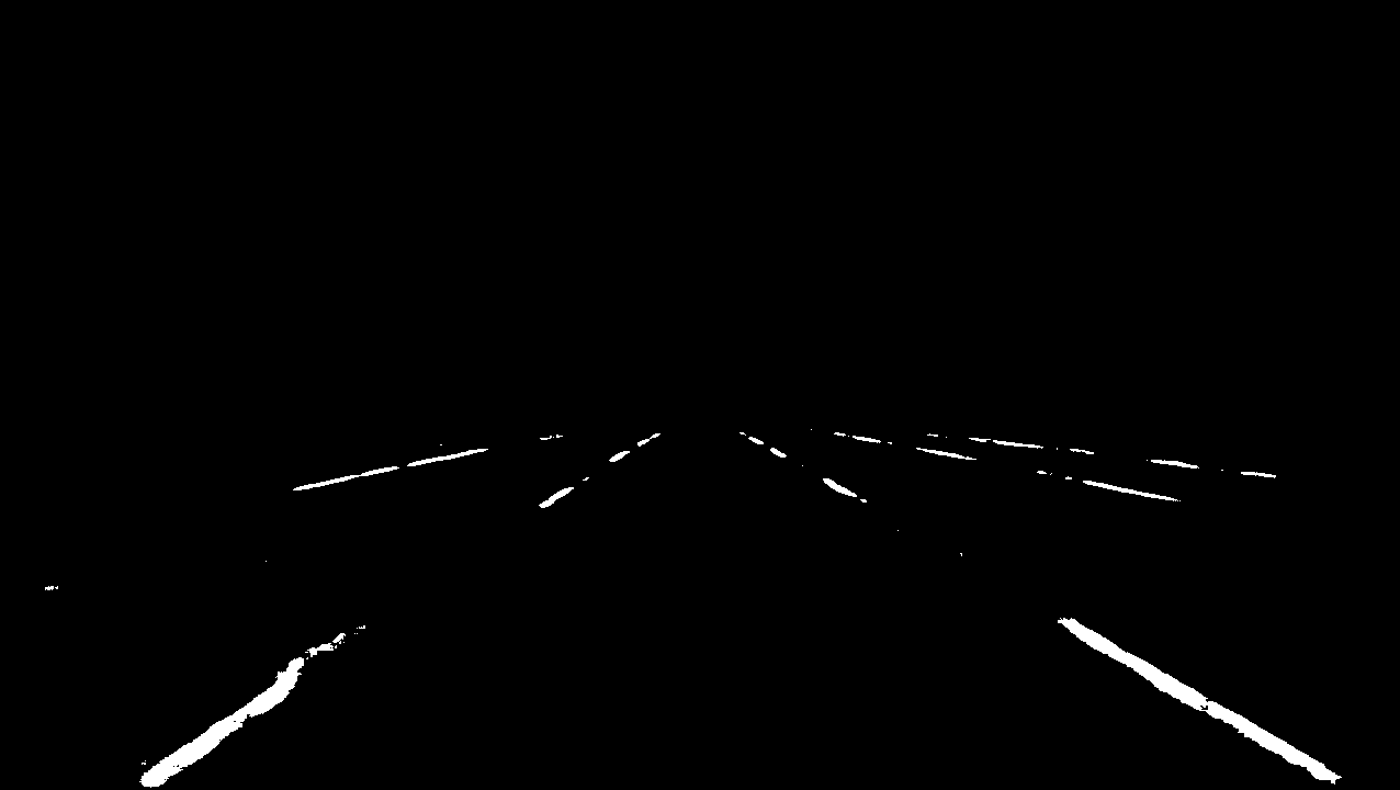
After annotating a few thousand images like that, we can train an actual detector on those initially generated labels. The output of such a trained model is displayed above.
These better detections (white) allow for a more accurate projection (green) of markers from the map into the image. In red, we show the initial projection (red) based on calibration and localization only.
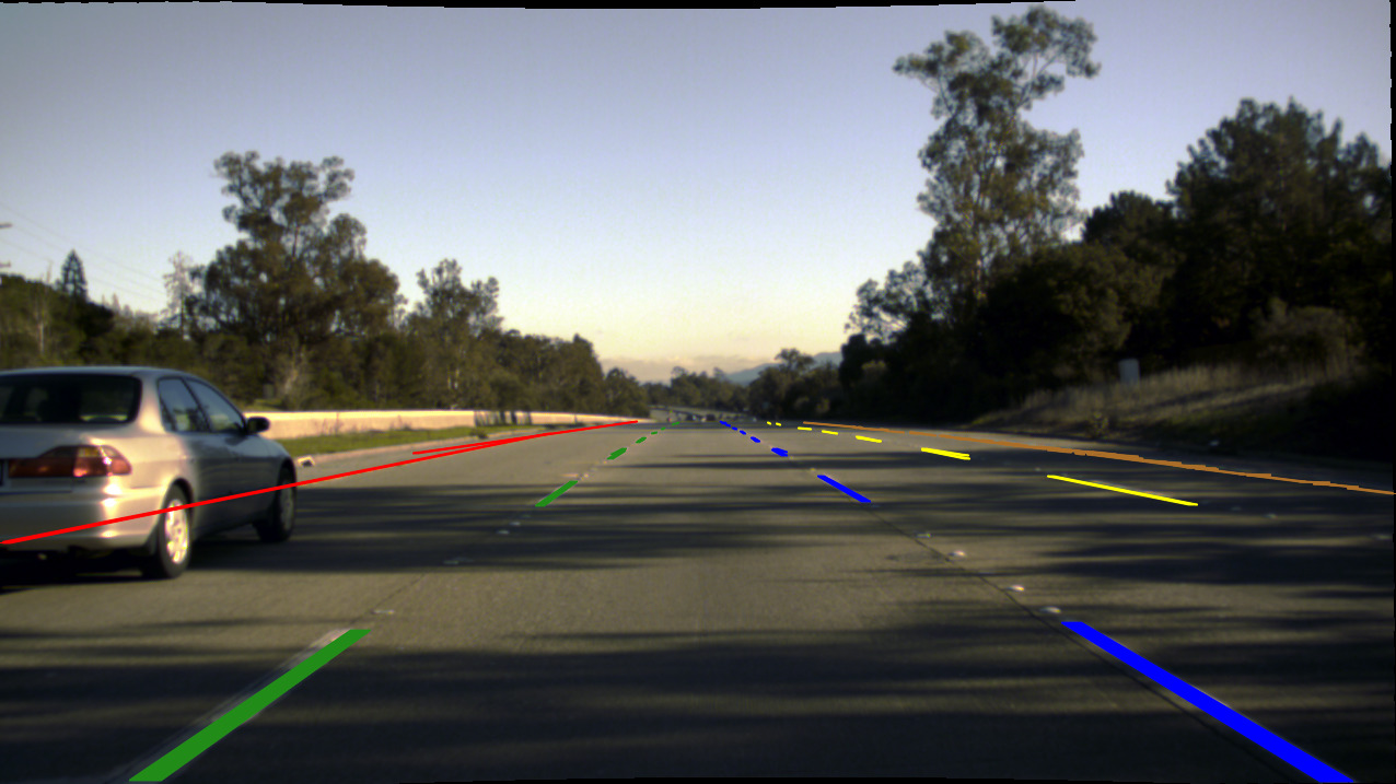
This image shows the corrected projection with map information such as individual lane markers and lane associations in the original image. There still are offsets because of occluded markers, inaccurate detections, and flaws in the auto generated map (for example, see the red marker on the left), but labeling up to the accuracy provided by this approach already is extremely time consuming and tricky.